|
Since ive started making my own pulse-jet ive realised that some of the things ive done were not necessary or there was a quicker way to do it. On this page im going to describe how to make your own pulse-jet using some of the knowledge i have gained over the last couple of months.
I will be describing how to make the pulso1 engine which i have built and therefore i can give better advice on how to do particular things. Ive modified the plans from the original by using direct injection instead of the normall carbureted method as for me it was easier to make.
| My pulso1 engine |
|
| And heres one i made earlier ;) |
THE FIRST THING TO DO
The first thing i would recommend doing is build the tailpipe section as this should be the easiest bit to do (if you have a set of rollers). The first thing you need to do is calculate the dimensions that you are going to have to mark out on the sheet of steel(mild or stainless) you can get the dimensions from the the image below. All measurements are in millimetres and inches. Ill be using millimetres because thats what im used to.
| click on the picture to get a larger image |
|
| Tail section of pulso1 with measurements |
From this diagram we can split the tail section into three parts.
- combustion chamber(big bit)
- conical section
- tail pipe(small bit)
For the combustion chamber the dimensions that need to be drawn out on the sheet of metal are
100mm x 298.45mm
The tailpipe section the dimensions are
530mm x 150.79mm
The conical section is a bit more challenging and for this i used a program that was written just for this purpose. You can find this on the making cones section. Just input the required values and the template required will be calculated for you, just print this off and thats it.
Next you need to take the sheet metal and cut out all the shapes you have drawn.
Once this is done you can start forming the peices of metal into the tubes or cones. This is best don on a set of rollers as this produces very accurate and smooth surfaces.
The two straight bits are easy to make just put them in the rollers so that the leading edge is parrallel with them and roll until the two ends curle round and meet each other.
The conical section can be formed by following the instructions on the making cones page
Making cones Once all the parts have been formed just check by placing them together to make sure you get a good fit, if not adjust until right but they shouldnt be too far out.
Now you can begin to weld first along the seams of each section and then welding them together. The best process when doing work on thin metal like this is to use TIG welding. This is however not always practical as TIG units are quite expensive but fortunately a MIG set can be used but you must be careful not to burn through the thin sheet. Ive found that doing the welding in short bursts is much easier than trying to do it in one go. you will probably have you own preferred way of doing this.
If you dont have access to your own MIG/TIG set then im sure there will be a workshop near by where some one will do it for you maybe even for free.
When welding all the sections together try and make sure they are all in alignment with each other, it just looks better at in the end.
Once all the bits are together you can now move onto the intake section!!!
THE INTAKE/VALVE SECTION
This section may be a little harder to do. The best way to make the intake is to use a lathe. First of all decide what you are going to make it out of, I used a ordinary bright bar steel because it was free, the best material though is aluminium which is lighter and easier to machine.
In the plans for this pulse-jet the intake consists of a venturi which haelps to draw in fuel when using the carbureted method. As we are using direct injection we dont need this bit at all.
As we have got rid of this part of the intake the amount of work required has probably been reduced by about 75% which is good.
The measurements for the pulso1 intake are shown in the picture below.
|
| Intake measurements |
Making it this way shouldnt take too long to do. If it is possable id try and make the cone and valve plate in one piece, this just makes the whole assembly more rigid.
Once all this is machined up the next thing you need to make is the valve limiter which helps to restrict the valves from moving beyond there elastic limit, they will still fail but this helps preserve them for much longer.
The exact shape and dimensions of the valve limiter i will leave up to you, there are a few different styles which you can employ. First you can have the valve limiter designed for the engine in the plans (shown below)
| Click to enlarge |
|
| Traditional valve limiter |
Another style of valve limiter that has been shown to increase valve life is one that consists of the valve limiter being much bigger than normal almost as wide as the diameter of the combustion chamber with holes drilled through it where the valves are usually situated. The enlarged valve limiter helps protect the valves from the heat and force of the explosions but will actually reduce the power of the pulse-jet aswell.
This is why the holes are drilled, the holes allow some of the force to close the valves whilst still protecting the valve from the heat etc. I havent actually tested this method yet so the exact size of the holes will have to be determined through trial and error.
Once this is all complete it should be ready to screw together. I only use four screws around the edge of the intake and this seems to hold it well enough so no more should be needed.
Once it is all bolted together the last thing you need to do is make some valves. I have drawn mine on Auto CADand allow me to obtain accurate valves. Below you can click on the link to get to My CAD drawing
| CLick to get the file(you will need Auto CAD) |
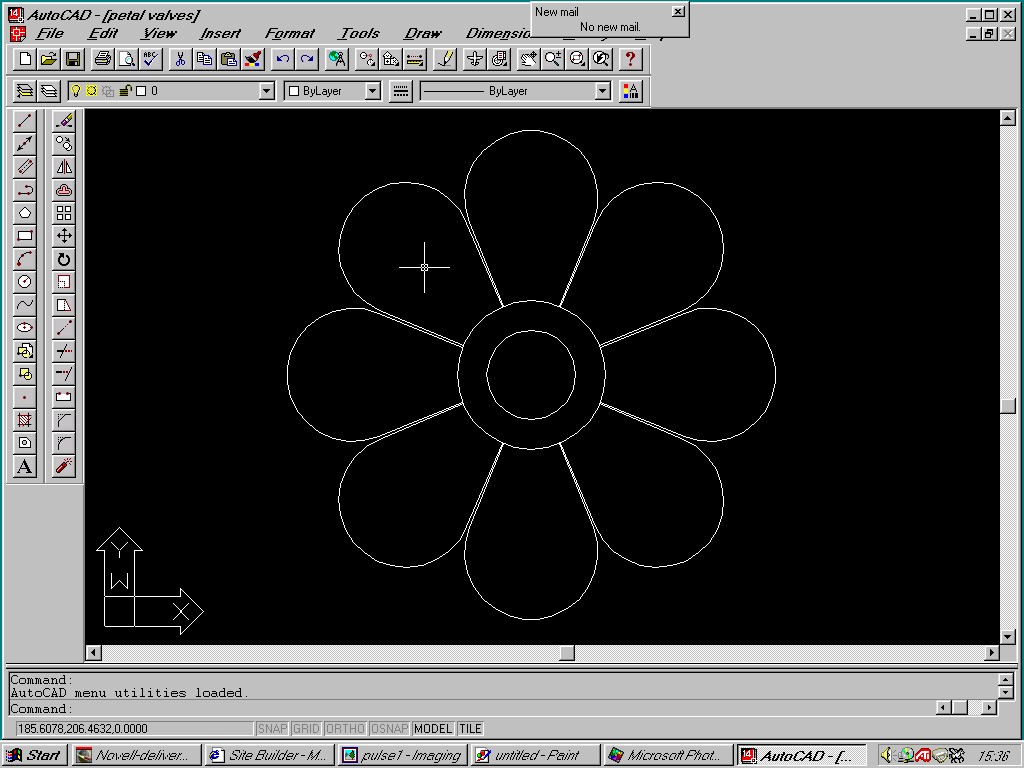
|
| Petal valves drawn on auto CAD |
Thats about it, all that remains now is to connect everything up and get her running. You will obviously needed some sort of ignition system, id definately recommend a spark plug as it allows much more consistant and better starting over everything else ive tried.
Let me just say again this is only a brief description of how to make the Pulso1 engine once its finished it may need a bit of tinkering to get it right, but pleases dont come back blaming me because yours doesnt work, sometimes you need to have some patience with these things.
|