Pulsejets
Pulsejet ignition circuit

Home

Downloads | About Me | Pulsejet photo album | My Pulse-jet design | My pulsejets pictures | Reynst/esnault Peltiere design | Lockwood/Hiller | Pulsejet ignition circuit | Jet engine Links | Contact Me | Project diary | General pulse-jet notes | Pulse-jet plans | Making a pulse-jet | Making cones

Electronic Ignition - there are quite a few images on this page so it may take a while to fully load

click here if you have any problems with your ignition circuit

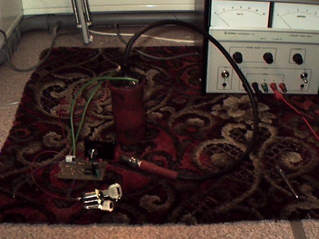
After many hours of developing/testing the circuit that was designed by bruce simpson i have come to the conclusion that for some reason it just wont work for me!  Now dont get me wrong when i first built it it did work but due to the constant messing around i did with it it has decided that it doesnt want to work at all. 
 
one of the problems i think with this circuit is the temperatures that the some of the components reached when in use even for only a short time.  I dont know if any one else has had this problem with this circuit but due to the restrictions in time that i have left before the project needs to be finished i decided to obtain a proper ignition circuit that would definately work and therefore allow me to test my pulse-jet with an electronic ignition system.
 
below is a link too the supplier i used to obtain the ignition circuit.

Click here to goto FLAMETHROWERS.COM

flame1.jpg

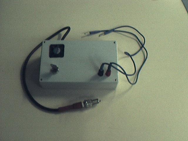
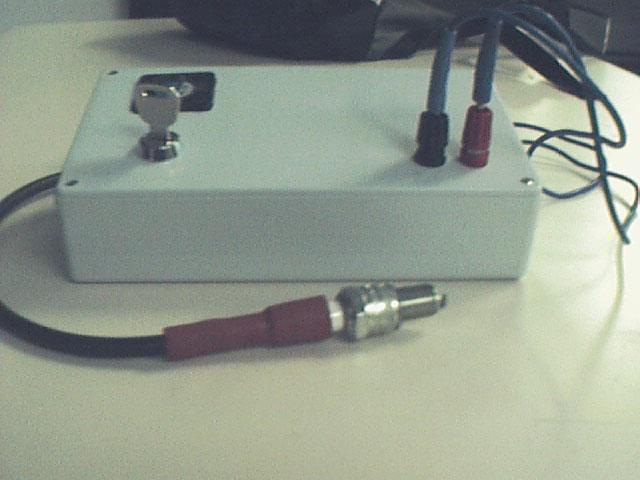
below is the rest of the ignition circuit page that shows how to build your own.  this circuit does work i have just run out of time and can no longer afford to tinker with it.

Gondolas in Venice; Actual size=240 pixels wide

Here you can find out how to build your own pulse-jet electronic ignition system.

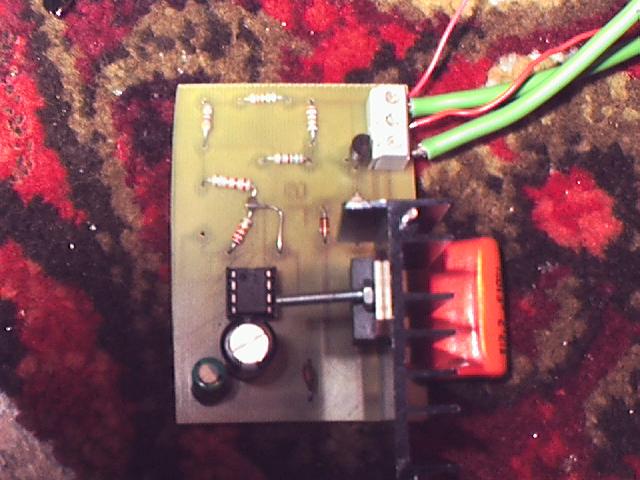
Ok the circuit i used is a bit more complex than some others on the internet but ive been told that its much better. anyway it works so im not to bothered. below is a picture of the overall circuit diagram.

ignitor1(2).jpg

click here to see a larger image

To make sure that you dont forget a few components ive made a list of all the components you will need to build your ignition circuit.

pic1.jpg

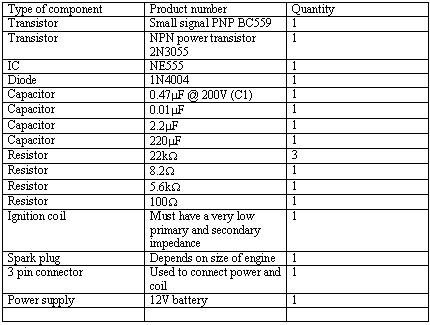
get the list now!

The list above gives the quantity of each component that is required for the circuit, i would however from personal experiance recommend getting a few spare transistors and 555 chips just incase. maybe even two of everything.

Ok now that we have the parts ready we can begin the construction. When i built the circuit i used some PCB board and etched the tracks onto that but you could also use veroboard although i dont have the layout for that so you will have to figure that out for yourself.

Once the circuit has been etched onto the board you can then solder the components in place. one thing i will say is that the large power transistor does occasionly get very hot! too hot in fact sometimes so id definately recommend the use of a large heatsink to dispers some of the heat and allow the circuit to function properly.

even with a large heat sink you still have to be careful, if you try putting anything more than 12volts 4amps through the circuit it will still get too hot so be careful.

pcb.jpg

The above diagram shows the circuit that i made before i discovered that the original circuit layout was wrong so you can maybe just see where the two resistors have been soldered togetherto solve the problem.

the PCB track layout is the new modified version that is set up as shown in the above picture but without the messy re-soldering, But at least it works.

With this circuit you can also vary the amount of sparks you get be simply replacing the botoom 22K resistor in potential divider setup with a variable resistor of your choice.

Ive taken some new pics of the circuit and its housing and will try and get them up before this week end.

ignitor.jpg

These two images show my ignition system in its final stage(i hope) i am however going to have to remake the circuit again as constant repairing due to testing has taken its toll and some of the copper has come away from the PCB and the circuit is difficult to make work now.

pic1.jpg

Now that you have the Ignition circuit completed we can now go onto the interesting stuff!.....

pic1.jpg